Text to CAD gets real: Tripo’s API and the prompt to part
Generative 3D just cleared the production bar. Tripo’s Text to CAD API moves text and images into manufacturable models, while parametric peers push full feature trees. Here is what CAD grade means and how to pilot it now.
The day prompt to part got practical
If you work in hardware, you have felt the drift. Generative 3D moved from eye candy to something your team can ship. Tripo AI’s new Text to CAD API is a clear marker. The company introduced the interface on April 2, 2025, with a promise to turn a sentence or photo into a manufacturable model that developers can automate inside their own tools. That shifted text to 3D from demo videos to software roadmaps, and it put pressure on traditional design pipelines. You can see the early coverage in Tripo AI launches Text to CAD API.
Dates matter. The April launch made the technology real for developers. By early October 2025, the market signal was unmistakable. Teams were stitching the same idea into end to end workflows, from design to simulation to print, and treating natural language as a first class interface for parts, scenes, and assets. What follows is a field guide to that shift, written for people who need the part to fit, the print to pass inspection, and the change order to trace back to a reason.
From pretty meshes to production parts
To understand the leap, separate three outputs that often get lumped together.
- Meshes for visualization. Triangle soups like OBJ or glTF look great and are light to render. They are perfect for games, ecommerce viewers, and cinematic assets. Under the hood, a mesh is just surfaces with no real awareness of dimensions or constraints.
- Meshes for printing. STL is the common case. These can be watertight, which means every edge belongs to exactly two faces and there are no gaps. That is necessary for slicing but not sufficient for engineering because there is no parametric history or feature intent.
- CAD solids for manufacturing. Boundary representation solids with features, references, and constraints, usually exported as STEP, Parasolid, or native formats. They carry parametric intent, which makes them editable in a principled way.
Most text to 3D systems start in the first category. Tripo’s API drove a bridge into the second, with export options that make sense for printing and downstream visualization, and with cleaner topology than early research models. The leap into the third category, true CAD grade parts, is what the industry is racing toward now.
What CAD grade really requires
CAD grade is not a vibe. It is a checklist. If you want prompt to part to be more than a demo, your models need four concrete properties.
1) Parametrics and a feature tree
A parametric model captures how a part is built. Think sketches, constraints, and features like extrude, revolve, fillet, shell, and pattern. Change a sketch dimension from 12.5 to 14.0 millimeters and the rest of the model updates predictably. This is how design changes propagate without breaking downstream steps. Without parametrics, an edit is surgery on raw triangles.
2) Tolerances and geometric intent
Robots crash when parts do not fit, and prints fail when tolerances are wishful. CAD grade parts carry geometric dimensioning and tolerancing, often under standards such as ASME Y14.5 or ISO GPS. That might be an H7 hole for a press fit, or a flatness callout on a mounting face so a sensor maintains alignment. The important bit is that the design encodes intent, not just shape.
3) Watertight solids and clean topology
For additive manufacturing, watertightness is about manifold geometry. For design, clean topology is about the absence of self intersections, zero thickness slivers, or dangling edges. Your solid should shell without exploding. If a model slices but cannot offset a face by 1 millimeter in CAD, it is not production ready.
4) Provenance and editability
An engineering team needs to know where a model came from, how it changed, and why. That means metadata, version history, and a feature tree that another person can understand next week. A black box mesh with no history is a dead end for compliance and collaboration.
Why this matters for robots, twins, and printers
- Robotics. A gripper jaw that must clamp a part with repeatable preload depends on tolerance stack ups, not just the visual shape. A single loose fit can mean a drop or a collision. Parametric parts let you embed those callouts and then regenerate a family of jaws for different components programmatically.
- Digital twins. A twin is not a screenshot. It is a live, simulated counterpart of your asset in a PLM or simulation platform. The twin needs accurate mass, inertia, and contact surfaces, and it must be editable. If the geometry is not true solids, your physics breaks or your update time balloons.
- 3D printing. Printers need consistent models. Slicers can patch tiny errors, but when you jump from prototype to production you must control wall thickness, hole compensation, and anisotropy. That requires design intent and a feedback loop from inspection back to parametrics.
The collapsing loop: design, simulate, print
The old loop looked like this: a designer models a bracket, an analyst remeshes it for finite element analysis, a manufacturing engineer reworks it for wall thickness and supports, a technician prints it, quality inspects it, and everyone goes back to change a hole size. Each handoff added delay and ambiguity.
The new loop is shorter, and it starts with a prompt.
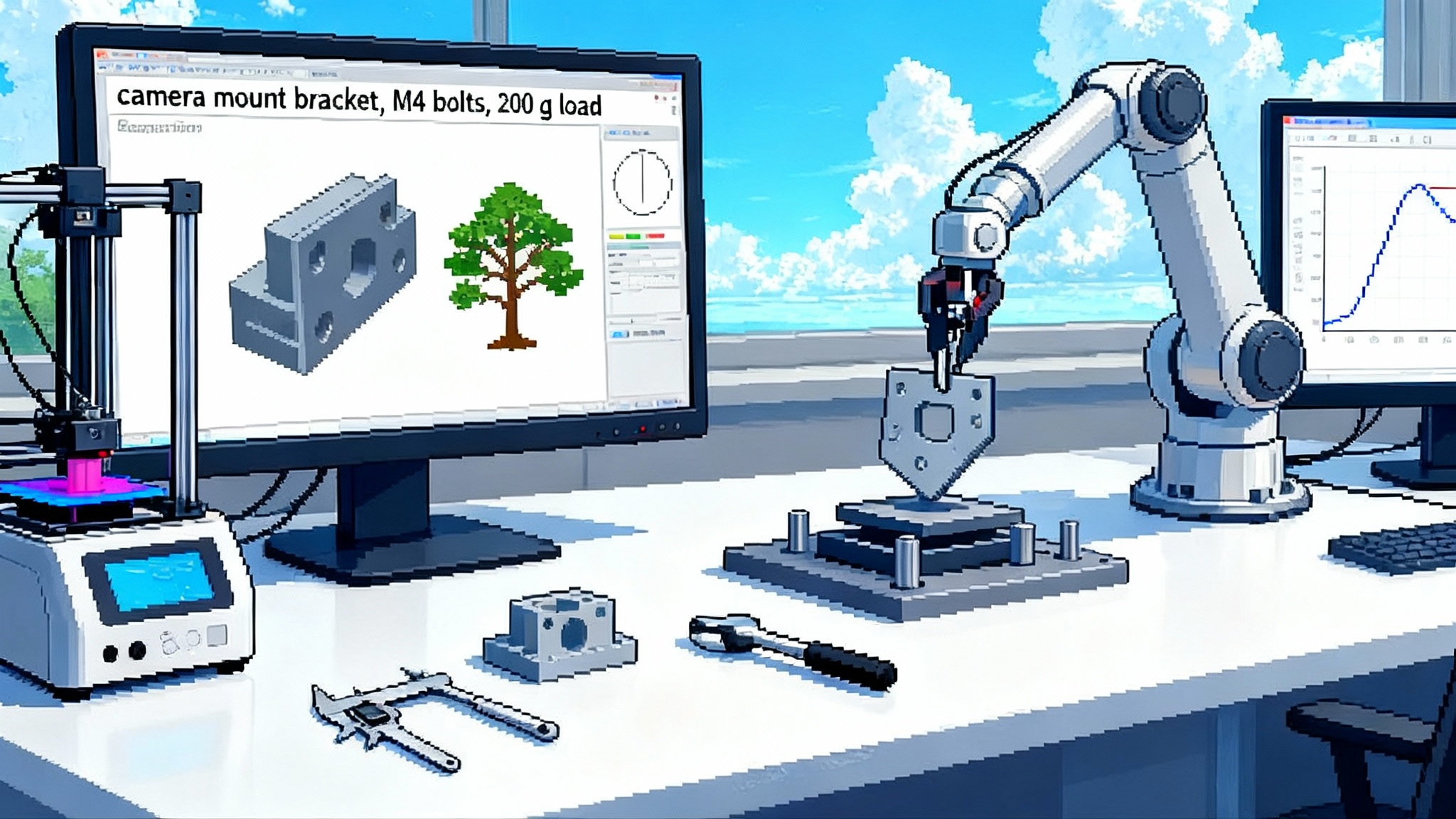
- Design. A developer asks for a camera mount bracket for a 200 gram load, two M4 bolts on a 20 millimeter spacing, filleted edges, and a cable relief. The system generates a first pass with a feature tree or at least a clean, watertight mesh.
- Simulate. A companion step applies loads and fixtures, proposes a material like 6061-T6 aluminum or PA12 nylon, and flags an overstressed fillet. The model regenerates with a larger radius and a thicker web. The key is repeatability across many variations.
- Print. The part exports to STL or 3MF with hole compensation for your printer’s kerf, then prints overnight. Measurements feed back as corrections to tolerances in the parametrics. The feature tree updates, not just the triangles.
Two loops later, you are done. What once took several people a week is now a single developer and a printer day. The time savings are obvious, but the real win is that every change links back to intent. You can explain the design in a review, and you can trace it in a change request.
Tripo’s API, strengths and limits
Tripo’s Text to CAD API matters because it gives developers an on ramp. It accepts text and images, it can return models suitable for real time engines and printing, and it slots into custom tools. The introduction focused on developer access and formats for downstream use, including visualization friendly options like USDZ and FBX. That is progress for teams building configurators and asset pipelines. It is not yet fully parametric CAD in the strict sense. The important takeaway is that Tripo made the first mile easy, and that first mile is where most teams stumble when they try to apply research code to production.
The second, harder mile is where the feature tree lives. You want editable sketches and constraints that open cleanly in common CAD systems. Some peers are attacking that problem head on from the other direction, by starting with CAD features and working backward toward prompts.
Backflip and the parametric push
Backflip, launched by the founders of Markforged, is an example of the other approach. The company focuses on turning scans and prompts into parametric parts. The public site describes native Onshape builds and exports to STEP, which are the formats you need to stay inside a manufacturing ecosystem. If you want to see how an AI product positions itself in CAD land, read Backflip’s AI Mesh to CAD overview.
The contrast is useful. Tripo gives developers a fast, expressive way to generate models that are topology aware and print friendly. Backflip focuses on rebirth into CAD, full of sketches and features. Neither is a complete factory by itself, which is fine. The point is that the stack is filling in from both ends, and large language models are starting to act as glue between them.
Where large language models slot into the manufacturing stack
Large language models will not replace your CAD kernel. They will sit around it and make it obey intent faster.
- Requirements to features. Translate a sentence like M4 cap screw clearance, countersunk, 90 degrees into a set of parametric features with the right standard dimensions and thread callouts.
- Constraint solving and regeneration. When simulation flags stress on a fillet, propose an updated radius and web thickness, regenerate, and recheck until the factor of safety clears the threshold.
- Design assistants inside CAD. Suggest feature patterns or scripts that encode common company templates so engineers stop repeating boilerplate work.
- Simulation setup. Autofill fixtures for a load case, meshing rules based on thin walls, and material picks tied to procurement data.
- CAM and printing prep. For additive, propose orientations, support strategies, and hole compensation based on printer profiles. For subtractive, suggest toolpaths that respect machine constraints and tools on hand.
- Quality and compliance. Write change descriptions that map to PLM fields, generate inspection plans tied to critical dimensions, and check drawing callouts against company standards.
If you are mapping agents into this stack, the broader ecosystem matters. For a view on how vertical agent stacks are standardizing I/O and control, see our take on the vertical MCP stack. For back end knowledge and retrieval that feed requirement parsing, compare the agent API for production. Finally, once you deploy these loops, you will want the zero code observability options that catch regressions in prompts and outcomes.
PLM, compliance, and IP in a prompt first world
Generative in production raises operational questions that are easy to ignore in demos.
- PLM integration. Every generated model should land in product data management with a part number, a revision, a link to the prompt and seed, and a record of who accepted it. If you cannot answer who changed what, when, and why, your audit will be a mess.
- Model based definition. If your sector uses model based definition, your generated solid needs annotations, datums, and tolerances that follow your drafting standard. That metadata must travel with the STEP file or the native CAD file, not live in a sidecar text file.
- Compliance. Medical and aerospace workflows require a design history file and traceability from requirements to tests. Prompts, seeds, and model versions belong in that history. Your supplier should be able to reproduce the exact geometry from that record.
- Intellectual property. Decide what prompts and outputs can be trained on, by whom, and under what agreements. For some teams, that means keeping the generator in a private environment, not a public cloud, and watermarking geometry for provenance.
Treat prompts as requirements. Treat the generated feature tree as code. Treat your PLM system as the system of record for both.
A practical pilot for your team
If you are a head of hardware, do not boil the ocean. Pick one of these pilot patterns and run it for 2 to 4 weeks with explicit acceptance criteria.
Pilot 1: Brackets and mounts
Low risk, high repetition. Define a prompt template with loads, hole patterns, material, and envelope constraints. Let the system propose variations.
- Inputs. Load cases, hole spacing, minimum section thickness, printer profile.
- Checks. Factor of safety above target, fillet radii above minimum, no nonmanifold edges.
- Outputs. STEP for CAD, STL or 3MF for printing, drawing with critical dimensions.
- Metric. Pass rate on quick finite element checks and printability without manual repair.
Pilot 2: Grippers and soft jaws
Tolerance heavy and geometry simple. You will find out quickly whether your pipeline handles hole compensation, datum alignment, and contact surfaces.
- Inputs. Stock geometry, jaw interface, target contact pressure, friction coefficient.
- Checks. Flatness and parallelism on contact faces, interference checks across the grip envelope.
- Outputs. Parametric features for pocketing and chamfers, plus a family table for size ranges.
- Metric. Cycle time to regenerate for a new component and first pass yield on the printer or mill.
Pilot 3: Small enclosures
Useful to test shell features, fillets, and draft angles. You will see where parametric regeneration breaks and how your surfacing holds up.
- Inputs. PCB outline, keepout zones, connector locations, ingress protection target.
- Checks. Minimum wall and rib thickness, draft angles for molding, venting for thermal targets.
- Outputs. Split bodies for top and bottom, mounting bosses, living hinges if applicable.
- Metric. Number of manual edits required to reach acceptance and time to a passing prototype.
For any pilot, expect to chain tools. Tripo for fast geometry and visualization assets, a parametric rebuilder or CAD kernel plugin for solids, a simulation preflight, and your existing printing or machining stack. The win is not one click. The win is one day.
Risks, limits, and how to de risk
Every new pipeline hides failure modes. Plan for them.
- False precision. A model that looks neat but lacks tolerances can pass a demo and fail in assembly. Insist on callouts for any critical interface.
- Topology traps. Thin slivers and self intersections may not show up until shell or offset operations. Add automated offset tests early in your checklists.
- Parameter drift. As prompts evolve, geometry can drift in subtle ways. Track prompt versions and freeze seeds for reproducible outcomes.
- Black box bottlenecks. If the only way to correct a feature is manual CAD surgery, you have not earned the speed gain. Push for editable sketches and named parameters.
What to watch next
- CAD kernels with native generative hooks. Expect leading platforms to expose more programmatic features for model regeneration from high level instructions.
- Hybrid formats. There is room for systems that keep a light mesh for preview and a synchronized solid for editing, with a consistent identity between them. That would let you move between real time and manufacturing without losing intent.
- Audit trails for prompts. PLM vendors will start to capture prompts, seeds, and model hashes as first class fields so that design history files are reproducible.
- Domain tuned assistants. Expect assistants that know your fastener libraries, printer profiles, and naming conventions, and that can write macros or scripts on the fly.
The inflection for physical product development
Text to 3D used to be a toy. With Tripo’s API in April 2025, and with parametric focused peers pushing from the other side, the loop is closing. We finally have the pieces to turn a sentence into a solid, to test it, to print it, and to trace it. The inflection is not that an assistant can make a pretty mesh. It is that a team can ship a part with the same accountability they expect from any engineered change. That is how generative moves from the demo booth to the factory floor.
Sources and further reading
For more detail on the launch and positioning, start with Tripo AI launches Text to CAD API and the overview of Backflip’s AI Mesh to CAD overview.